Rocky Gap and Antietam

Our first shake-out trip with “Serenity” went to Rocky Gap State Park in Maryland, a couple of hours drive. The idea was to use whatever season we had left to test the van, equipment and attitude before we mothball her for the winter. Rocky Gap is close, easy to get to and quite nice, it has a large lake with limited hiking but overall is pleasant for a quick outing. We squeezed Serenity between other vans, trailers and tents and with early dusk, didn’t have much time to explore before starting the fire and shutting down for the evening.

There is a weird atmosphere in these shared camp grounds, neighbors on all sides and even though everyone is considerate, the background noise of “camping” is always there. People walk with bouncing headlights to and from the washrooms keeping the dog on alert. Having the dog on-leash (a long one) kind of works but it would be great to have her free to roam the site and explore.

Overall, the camp-site and park are nice site but there isn’t much to do – other than the lake itself, the trails are not very inspiring and the entire park is boxed in by roads and agricultural land. Its alright for a night out but I would not want to spend more time there

The dog wakes up ~ 6am no matter what which means that we are going for a walk. Its dark in October and the landscape is not super exciting. Overcast as well, so no real good photo opportunities during sunrise but we put in a 2h walk along the lake shore to spend the time. When we come back, quick breakfast and departure, heading roughly back.

On the way back, we stopped over at Antietam and drove / walked the various locations. Its close but I had never been there and like all battlefields, the idyllic, pastoral settings creates a very disconcerting contrast with the description of the slaughter that happened here. Unlike Gettysburg, Antietam appears very small in size. The sheer number of soldiers and artillery that squeezed into this tiny area must have been staggering. It probably contributed to the death count simply because in close quarters communication failed with smoke obscuring the field and lines never clean. Constant skirmishes and outright barrages without the ability to retreat, reform and resupply must have made for a horrifying experience for everyone who lived through it. In the end, there are no winners, just losers.

It didn’t help that it started raining hard and neither of us was really in the mood for more hiking, soaked, cold and with home so close by, we heading back.

Overall, Rocky Gap can easily be missed but Antietam is worth a visit – maybe take a guided tour next or read up beforehand.

Serenity

We bought a campervan! She (of course female) is a 2015 Pleasure-Way Excel based on a Ford Econoline 350 with the 5.4L Triton V8. She has 40k miles on the clock and we found her in Florida baking in the sun at a dealer. Her price was good, the condition decent and I flew out to see a client and on my way check her out and – if she passed – drive her the 750miles home.

She is called Serenity after the “Firefly”-class cargo hauler from the short-lived Sci-Fi Series. Its one of our favorites and the dependable, slightly worn but lovable ship is a perfect namesake for the van that allows us to explore.

Quick note on why we selected this specific van. We knew we wanted a Class B, basically a campervan, not an RV. It had to be 20 feet or less so it fits into State / National Park camp grounds (not RV parks) and basically needs to remain maneuverable without tugboats. At the same time, there is of course the requirement for additional luxury like a flush toilet, proper bed, a TV / DVD player, air conditioning etc. Basically, the higher end Class Bs have all the amenities but remain on a normal cargo can footprint, something that can be driven around towns and smaller country roads without issues. There are a huge number of vans to choose from and they all seem to be based on Ford, Dodge or Mercedes Sprinter chassis with either a dedicated cabin or – far more common – a converted people hauler. Virtually all of them are too tall, the place where we park her has a hard (=structural beams) ceiling of 9’3″. This really limited the model choice but also focused us on the type of van we could get, basically the pre-2015 Ford E350 Econo Line. And those vans were the chassis for a few campervans, namely the Pleasure Way models from Canada.

Now I started looking specifically for this model, 2008 up with a max of 50k miles. A few of them have V10 engines which is nice in mountains but basically means that one has to haul a fuel tender since the fuel tanks are the same size. I could not find any Diesel engines which would have been really nice from the torque perspective (and mileage), with all the amenities, these vans are actually quite heavy. And lastly, the Pleasure Way Excel specifically has a widened cabin, 2-3″ on each side make a huge difference inside and give the van a “fat rump” which of course led to her name.

We test drove one in Maryland but couldn’t agree on a price, it was in pristine condition but quite old already and had a fair number of miles. Then a few months later, one came up in Oregon (V10) and the one in Florida that we finally bought.

Buying a campervan basically combines the worst parts of buying a house with the worst parts of buying a car. One deals with a used-car dealer with all the greasy, fake smiles, friendly chumminess that is so repellent that I’d rather pay sticker price than shake their limp hands. Add to that that a RV is fairly complicated. Its got all the 12 & 120 V electrics, 3 separate water tanks, a full propane system with tanks, lines etc, A/C plus of course the van itself. Yes, I spent 6 hours checking it out and having them repair all sorts of things but in the end didn’t check all the parts that the dealer – quite skillfully hid.

First Look

The deal was struck and I took off, basically heading straight north on I95. Driving her was a little daunting, I don’t really drive anything larger than an SUV ever and being in Flordia didn’t help, people seem to not use indicators at all. The radio is complete garbage, the standard Ford “comes with the truck” kind of thing and despite trying I could not get anything other than Christian Rock, Christian Country or Christian Talk shows for the next 600 miles. And of course, she is slower in top speed, acceleration and – crucially – deceleration. The plan was to head North, find a Walmart, eat, sleep and keep going.

A night at Walmart….

That’s pretty much what happened as well and 23h later with 750 miles down I got her home. Where she fit under her roof just about (with 2″ to spare).

Weather Station – Receiver

I had written about my weatherstation, why I use Xbee rather than WiFi and and a few posts about sensors and placement.  The last remaining topic is to talk about receiving / displaying the data and sending it to the internet.

This receiver / basestation / coordinator has been the ugliest component of the build, likely because I wanted it to do too much. It is supposed to be an actual weatherstation with interactive display, a clock and my central hub for my XBee network.  While it has been a useful exercise in learning how to program wildly different requirements it quickly exceeded what an Arduino Uno can do.  I had to move to an Arduino Mega (knockoff from Aliexpress, by the way, works great) which in turn meant that the Sparkfun WiFi shield doesn’t work anymore.

The entire assembly is an unholy mess of wires and connectors.

Ugly but it works (Kind of)

Components:

  • Top right: Standard LCD Display with shield allowing me to communicate with I2C (about that later)
  • Left: Arduino Mega, Aliexpress knockoff.  This is the Coordinator
  • Middle: breadboard with XBee (in coordinator mode), real time clock (top) and a TMP36 analog temperature sensor.
  • Bottom:  Arduino Uno with a WiFi Shield connected by I2C to the Coordinator Arduino.   I added an external antenna to the shield(black lead left side of image)

How it works

The Xbee Weatherstation sends data every 30 seconds from its position on the roof.  The Coordinator receives the data, displays it on the LCD shield and sends it via I2C to the connected Arduino Uno.  The Uno is connected via its WiFi shield to ThingSpeak and sends it the data as it comes in.  The Thingspeak data is embedded into this blog.

The code is here:  Mega (Coordinator) and WiFi Conector (Uno) and most of it is pretty straight forward but inelegant.  Especially the coordinator “grew” in scope over time but it has been pretty stable, so I left it.  The Arduino Mega still has plenty of memory and ports left so there is no real reason to tighten the design =re-write).  If it ain’t broke and all that.  The LCD shield has shown to be very limiting.  I wanted to show the time derived from real time clock as well as the current weather conditions with in/outdoor temperature, outdoor humidity, wind speed, wind direction, gusts rain rate, I just had too many numbers to display at any time.  I personally can not stand displays that automatically scroll through values and hence I enabled the buttons on the shield to switch between the states.  Up Button now shows the outdoor temperature and humidity.  Right Button the indoor temperature of the TMP36 (which by the way is frequently reporting -100 C data, likely bad connection).  Button Down is Barometric pressure, Button Left is Wind Speed, gusts and directions in degrees (need to make lookup table for actual compass rose values).  The “Select Button” switches the display to Rain Rate.

The Mega uses I2C to communicate with the LCD shield as well as the Real Time Clock and hence has to serve as master for the devices.  I2C is a pretty elegant protocol as it enables communication with only two wires (and ground) but I found it hard to learn until I found the I2CAnything library from Nick Gammon (thank you!).  I have to send float values across the I2C bus and doing this without the library exceeded my programming skills.  I2C also allowed me a pretty straight forward connection to the Arduino Uno whose sole purpose is to drive the WiFi shield.  The Uno is in “slave mode” and waits for data to be sent to it, the sends it to my Thingspeak channel.

Aside from being badly soldered (LCD shield), being a mess on a breadboard (everything else), expensive (2 arduinos,1 WiFi shield) and using a TMP36 which gives me issues its working perfectly!

To clean up, I bought an Adafruit Huzzahh ESP8266 breakout board, the promise is / was that it is a fully-fledged Arduino with integrated WiFi, it just has fewer ports. The goal was to connect it to the Mega and scrap the Uno / WiFi shield to make the entire package cheaper and more transportable. Turns out the ESP8266 is well documented and can be used as a I2C master but does not currently work as a slave.  This is a problem since I can not see myself re-writing the entire code for the Mega and allow the ESP8266 as a Master.  Apparently, there are tricks to use systems with 2 masters but this is getting unwieldy.  I could send the data by serial port (the Mega of course has many serial ports left) but as stated above, reliably sending floats is something I yet have to learn.


For now, I decided to live with the system but pack it into a more self contained box, use actual boards and soldered connections rather than the breadboard and stick it into a box that hides the mess.  I will also need to clean up some code (wind direction as actual compass directions for example and find a system to set the clock manually, I didn’t appreciate just how much the RTC drifts over time).  After that, I will focus on other projects and eventually move the entire coordinator / display into a PC (I have an old Linux laptop somewhere) and was itching to learn how to use “Processing” anyway).

Side Project – Microwave Motion Detector

I wanted to build a driveway monitor that alerts me in my office when a Fedex truck makes a delivery or evil Zombies looking for fresh brains.  Our driveway is reasonably large and I thought that a standard IR motion detector may not be ideal. Those tend to have a pretty short range and also get triggered easily by deer for example.  What I was looking for was a long range, detector that could be tuned to just about the mass of a car (assuming Zombies arrive by car).

Enter the XYC-WB-DC module that I picked up on E-Bay for a couple of bucks, it promises 360 degree, tuneable motion sensing.  This YouTube video explains well how the sensor works but unfortunately, otherwise, there is very little documentation in English.  It seems to have been designed as a motion switch for light fixtures etc in factories where high ceilings are more common. It does sense motion through walls which I thought would be neat but in the end turned out to be a nuisance.

Setting it up was pretty straight forward except that I broke a soldering point on (both) devices.  The soldering points are directly on the board and when the cable that I soldered onto it snapped off accidentally, it took the entire point and connection with it.  Now I can not figure out a way to attach a resistor that tunes the delay after activation.  In principle this isn’t a big deal but the default 30second delay is a nuisance to set up and I decided to shelve the project for now. While I had it running, the real nuisance was the lack of direction and its ability to penetrate the table top or enclosures.  For some applications that is a useful feature and I may get back to it in the future, for now its back in box.

Weather Station : Transmission

My last posts discussed a little why the world desperately needed yet another weathers station, where I would place it and why and how the sensor package looked like. Now lets talk a little about data transmission.

Why

Given the position of the Sensor Package on roof of my house, a wireless solution was required.  Question is, which wireless system to use?  All the cool kids nowadays use WiFi modules like the ESP8266 to connect directly to the house WiFI network.  Its the obvious and the cleanest way of doing it as it also allows programming the Arduino over the wifi connection.  I did not go down that route for three reasons.

  • Wifi is pretty bad up there and I would have to put a repeater near it (inside the house) to make sure I have a reliable connection.
  • I really wanted a true mesh system that allows me to add sensors anywhere on the property, basically a backbone for home automation, alarms, chicken coop, hydroponics etc.  The more sensors (within reason), the denser the mesh, the more reliable the communication.
  • I thought building a radio communication from “ground” up mostly as a challenge to myself.  Yes, this was the real reason.

In the end, I chose to use the Xbee standard from Digi since it is a very well documented flavor of the even better documented Zigbee (IEEE 802.15.4).  Xbee allows true mesh radio systems with relatively low programming, a lot of the network maintenance code is already build in.

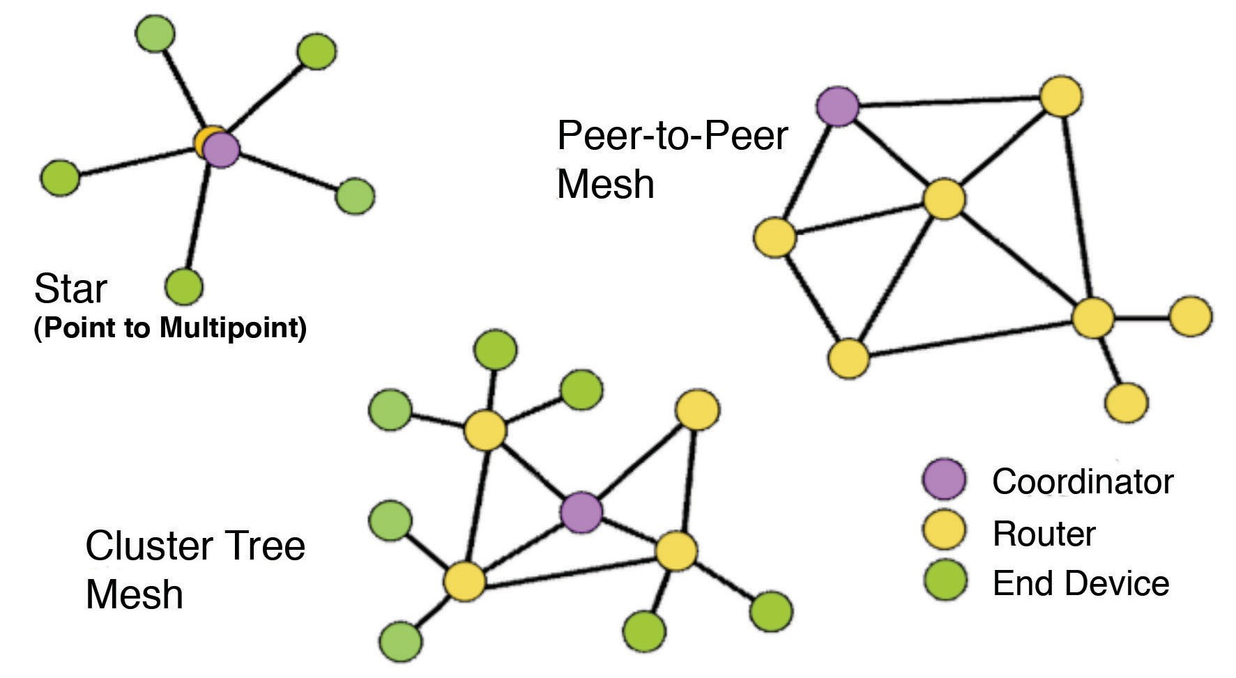
As a recap on mesh networks, this page explains them very well. The advantage is that it allows good network expansions since the devices form a communication chain. As long as there is a coordinator, a remote device can send data across multiple “hops”.  The downside is that the data transmission rate is pretty low – a lot of bandwidth is burned just to establish the mesh itself.  Eventually, my house-network will have maybe 25 sensors and devices permanently powered that periodically send a short burst of data (weather stations) or battery operated end devices that only come online when they have something to send (door / window sensors, driveway sensors etc).

Mesh Networks

Lastly, mesh networks have a few interesting features, in that a single device attempts to communicate with many other devices and assesses which signal strength (RSSI) is the strongest.  For static sensors, this is not a big deal.  But in the back of my mind I had the idea of using this system to track small, mobile objects (=cats) and use the RSSI as a means to identify where they are.  To be honest, I wanted to build it because several intelligent and knowledgeable engineers told me that it is a bad idea and I thought it would be cool to prove them wrong. But that is a project for later.

xbee-rssi

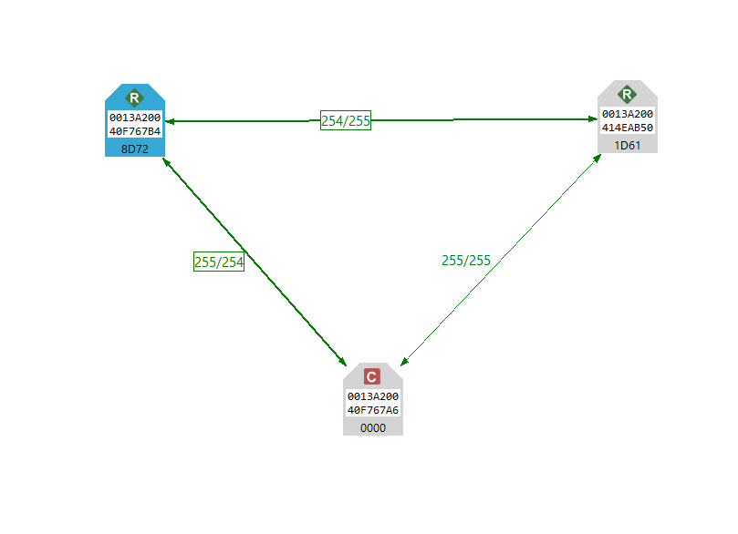
The picture above shows three sensors (coordinator, weather station and a Laptop (blue, left) communicating with each other.  The signal strength for each path is shown on the arrows.

Back to the weather station.  I have one XBee configured as Router (inside the Sensor Package) and another as Coordinator connected to an Arduino which also doubles as a clock, display unit and general “hub”.   But while Arduinos excellent in interacting with the world, their single-thread processing and limited storage make crummy computer replacements.   Eventually (so the internet tells me) I should move the coordinator to a Rasperry PI but for the same effort, I probably just use an old laptop.  As the my coordinator, I ended up using a Arduino Mega since an Uno already ran out of storage.


How

To run an Xbee inside a mesh as described above, I need to structure the data into a package that the coordinator understands and I spent way too much time trying to figure this out by following well-meaning YouTubers.  In the end I bought the excellent book “Building Wireless Sensor Networks” by  Matthijs Kooijman which made understanding and implementing the network extremely easy.

Alright so we have the weather station Sensor Package on the roof sending data every 30 seconds to the coordinator.  The entire sketch is on Gitub.


void sendPacket() {

detachInterrupt(AnemInterruptPin); //stop interrupts while sending package //this is probably overkill but I dont like taking chances with interrupts during transmissison
detachInterrupt(RainInterruptPin); //stop interrupts while sending package

WindSpeed = (AnemCount / sendInterval * 1000) * WindFactor;
MaxGust = (MaxGustCount / gustInterval * 1000) * WindFactor;
MinGust = (MinGustCount / gustInterval * 1000) * WindFactor;

if (MinGustCount == 0 || MinGustCount == 1000) { //messy code. Cant reset the MinGust to 0 since it will always be lower than any reading. Setting it to some large value
MinGust = 0;
}

MaxGustCount = 0;
MinGustCount = 1000; //messy way of doing it

RainRate = (RainCount * RainFactor); // accummulated raind during the interval. The true mm/[time] is done elsewhere
AnemCount = 0;
RainCount = 0;

In this function, I detach the two interrupts since I am paranoid that an interrupt will disrupt the transmission sequence. It may not be necessary but I felt it was safer. Then the wind speed is calculated from the data sheet of the anemometer, gusts are calculated as the delta between the maximum and minimum wind speed of 5 second intervals within the 30 second send interval.


// Prepare the Zigbee Transmit Request API packet
ZBTxRequest txRequest;
txRequest.setAddress64(0x0000000000000000); //I assume this is broadcast.


// Allocate 40 payload bytes. 10 parameters = 8x4 bytes + 1 byte.
// Appending this needs appending on the Coordinator as well - shouldnt one be able to use the length?

AllocBuffer<41> packet;

// Packet type, temperature, humidity
packet.append<uint8_t>(1); //this is the additional byte.
packet.append<float>(dhtT); //each parameter has 4 bytes
packet.append<float>(dhtH);
packet.append<float>(bmpT);
packet.append<float>(p0);
packet.append<float>(WindSpeed);
packet.append<float>(RainRate);
packet.append<float>(windDirection);
packet.append<float>(MaxGust);
packet.append<float>(MinGust);
packet.append<float>(millis()); //place holder for battery status or the like. not relevant

txRequest.setPayload(packet.head, packet.len());

// And send it
xbee.send(txRequest);
attachInterrupt(0, AnemAcq, RISING);
attachInterrupt(1, RainAcq, CHANGE);

The data package for the Xbee transmission is assembled very closely to the examples in Kooijman’s book. I was concerned that the package was getting too long but this has not been an issue yet. The package consists of 1 byte + 4 bytes for each parameter that I send, so a total of 41 bytes is sent every 30 seconds. (The code comment is wrong, it should read 10 parameters = 10×4 bytes) It works very well and the library takes care of the heavy lifting (HEX codes etc). One improvement would be to calculate the package length automatically but since the structure doesn’t change, its not a big deal. Obviously, every new measurement type increases the package on the sending and the receiving end by 4 bytes.


Improvements for future

I mentioned before that Xbees are perfect for “beacon-based” transmissions, i.e. let the coordinator run the timer and requests the data from the router rather than have each route send based on their own time.  This keeps the channel much more controlled especially when multiple Routers or end devices are in the system and space needs to be made for non-scheduled transmissions (such as status changes, door openings etc).  I’ll do that next year when the next round of sensors is installed.

One additional feature I did not install yet is “store and forward”.  In principle, radio communication is always slightly messy, environmental effects affect signal strengths, power outages can occur and in general “stuff just happens”.  Especially longer transmissions with a single checksum may get garbled.  The Xbee system has some safeguards but if power is lost to the coordinator for a few minutes, data will be lost.  Implementing a system to store incoming data until its confirmed as sent is standard in many wireless systems and likely something that I will look into in the future as well.


My next project is to improve the receiver end (coordinator), at the moment its a naked Arduino with a LCD display and second Arduino hanging on it with a WiFi shield.  It works but its very messy


Weather station: Sensor Package

I explained why I am building a weather station and where I intended to place it.  I realized that my writing is “narrative” and not instructive and from now on, I will try to be more concise and separate my posts into “why” and “how”.

Sensor Package

Why: I discussed the design requirements in the previous post, so I keep this short.  The requirement was for a robust, powered but wireless sensor package that survives environmental challenges for years and accurately reflects its micro climate.  The system is also based on a single Arduino Uno because I am not (yet) at the stage to program the ATmega328P directly.  This was is my first Arduino project, so the process of getting it done is very slow and my code is sloppy, badly annotated and inefficient.  But it works, don’t hate me.

Pretty early I had to decide how I wanted to structure the communication.  Since I was building a XBee network with mesh capability (about that later), I did not want to go into “streaming” mode, its too slow, too unreliable and in the end overkill. The proper way of doing these networks is “beacon-based” where a central station (coordinator) requests a data package.  While this is the right way of doing it, duplex communication over Xbee was a bit too much for me as first project and I put the timer on the sensor package. For the sampling interval, I now chose 30 seconds which I will reduce as soon as more sensors occupy my network.  For this season however, this is fine.

How:  Hardware:  Arduino Uno, DHT-22, BMP180, XBee Radio, and the Sparkfun Weather Meters.  Scraps of duct tape and double-sided tape to keep items from shifting inside the junction box.  Various cables and generic connectors.

Code  All code is in GitHub in this project.

General comment on code: I am not a programmer and the code evolved over a few months worth of trial and error. I am sure it can be improved and streamlined and in the end I will likely do so.  For example, I rely heavily on global variables and floats, a very bad practice on Arduinos.  For now it works.

The DHT22 is connected to Digital Pin 4 and uses a standard library. I trimmed down one of the examples and it generates temperature and humidity data as soon as its function is called.  Its pretty easy and I stick with Celsius since I can’t get my head around Fahrenheit.

The BMP180 pressure sensor is defined as an object and I (full disclosure) I am not entirely clear on what the code does.  The code has many redundant checks whether the sensor properly initialized or not but I don’t use any of them in subsequent communication.  I will revisit this sensor next year, for now it gives me reliable data.

The Windvane was the one device that looked the most complicated but turned out to be very straight forward.  It relies on a series of resistors to generate 16 distinct voltages depending where its pointing toward (datasheet).  This in turn means that it can rely on a single analog pin (quite ingenious).

wind-rose
Diagram from Datasheet

The code uses 2 arrays, the first are the nominal values that we expect from the resister/voltage output.  The second array is the associated wind direction in degrees. The measured analog value (vaneReading) is sequentially compared against the values of the first array and the value with the smallest difference is chosen. The corresponding array position is then looked up in the second array which holds the wind directions. This should allow for some fluctuations of the sensor reading (temperature for example).


void windRose()
{
  vaneReading = analogRead(VANE_PIN); //read the analog signal from the Windvane, optional: float voltage= vaneReading * (5.0 / 1023.0);

  for (n = 0; n < 16; n++) //16 possible positions of the windvane
  {
    diff = vaneReading - pgm_read_word(&vaneValues[n]); // calculate the difference between the actual reading and the ideal valuye from the array
    diff = abs(diff);

    if (diff < allDiff) { //select the vaneValue with the smallest difference to the ideal. The vaneReading is a little noisy, this seems to take care of it
      allDiff = diff; //allDiff = smallest difference from the array compoarison.  Kind on bubblesort.  dont really need this value, for debugging
      allN = n; //allN is the position in the array with the smallest different between ideal and measured
    }
  }

  windDirection = (pgm_read_word(&vaneDirections[allN]) / 10); //report winddirection
  
  diff = 1000;  //set diff to something high so that the routine doesnt get stuck
  allDiff = 1000;
}

}

The rain sensor and anemometer work differently, they rely on interrupts to trigger counters. Arduino Unos have 2 interrupt pins (Pin 2 = Interrupt 0 and Pin 3 = Interrupt 1) and programming them is pretty straight forward. The math however is a little different since the interrupts are counted during the interval time, by definition they are averages,  “interrupt counts / interval time”. For wind speed, it turned out that the interval time is too long, the values are all smoothed out. Hence I added another timer to measure gusts.  For the code itself, I relied heavily on Kevin Kessler’s blog post installing the exact same sensor package.  His programming skills far exceed mine and for good code, go there.

As a (unnecessary?) safety precaution, I turn the interrupts off during the assembly and transmission function.  I’ll cover the XBee transmission in my next post.

Below the Fritzing Schematic.  I likely made mistakes in the wiring, first time working with formal layout programs.


sensor-package

Outside considerations

Alright.  After not just one but 2 (!) quasi scientific / philosophical posts about the concept of an entirely superfluous weather station (overkill), lets get into the actual meat of it.

Lets look at the hardware and sensors that need to live outside.  I decided that I needed temperature, humidity and barometric pressure as bare minimum.  I really wanted wind speed, wind direction and gust levels.  I read about other weather stations having UV monitoring but considering that I would have it underneath trees, I didn’t think there would be much worthwhile data.

So, as sensors, we have a DHT-22 (temp, humidity) and a BMP180 and a Sparkfun Wind speed and direction, gusts, rain gauge.   The DHT22 and the BMP180 are very well documented and supported, many, many examples exist of them being integrated into Arduino projects.  The Sparkfun wind speed and rain sensors are a little less well documented and functionally a little bit more complicated as well.  All sensors are connected to an Arduino Uno and – eventually – housed in a Home Depot electrical junction Box.  In the photo below, you see the assembly before attempting to tighten the cables and you also see the black antenna cable that connects to the XBee radio.  That cable by the way lives inside the junction box because I didn’t trust it to survive outside.  This is far from ideal but it does work.  I’ll write later about the entire wireless hook up.


sensors in a box

A couple of comments about the box.  I realized that the weather station would have to be on the roof of the house and relatively difficult to reach so I put quite a bit of thought into the box itself.  It had to be as watertight as possible, resist burrowing critters, rust, leaves falling, heat up over +40 C and below -20 C.  A standard electric junction box from Home Depot does just that. I drilled 2 holes, one on the left for power supply and the wind/rain sensor cables.  A second hole allowed me to connect the DHT22 and the BMP180 and place them on the outside of the junction box.  That in turn means I can more or less seal off the main electronics compartment and keep the Arduino relatively safe.

View into the sensors


To protect the dangling sensors, I took some left-over PVC piping and glued it to the box with standard plumbing glue .  I used little scraps of duct take to secure the pins to a couple of crudely-cut breakout boards since I didn’t want to solder the sensors themselves.  I did this mainly so that I can swap the sensors out if they are damaged for example. This connection is definitely a weak point and I am keeping an eye on it.  Not happy but it works for now.

Lastly, and not shown in the picture, I covered the bottom end of the PVC pipe with a layer of wire mesh.  You can buy the little patches of mesh at home depot as well, generally used to repair screen windows and doors.  Basically, where we live, if a critter can get in, it will and the screen should prevent this.  In the end, turn the entire assembly upside down and mount on the side of the chimney.

Mounted weather station

From the photo above, one can see the whole assembly.  The white PVC tube that contains the humidity, temperature and barometric pressure sensor points downward and air flows past it freely.  It is nearly always in the shade and about as easily accessible as anything can be on a roof.  The anemometer, wind vane and rain gauge are installed on an old VHF antenna pole.  Its not as high as I want but the whole assembly is rock-solid.  One issue may come up in the winter when I fire up the wood burning stove.  I don’t actually know how much it warms the bricks up but this nearly 3 floors above the fireplace and bricks are pretty good insulators and the sensors don’t even touch the brick themselves.  I don’t think its a big deal.  And if the sensor does get heated, its a sign that I am wasting energy, so that would be an interesting outcome.  I wonder what he wood smoke does to the anemometer and wind vane.  Probably nothing.

By the way: power.  Originally, I had intended to make the entire thing solar powered which of course causes quite a few design issues.  Low power, sleep mode, solar chargers, all of which I had planned until I went on the roof and removed the old VHF antenna off to make space.antenna

Turns out, that antenna was quite a beast for its days and had a directional motor underneath that could be controlled from a dial in the bedroom.  The photo on the left shows the bottom assembly after unceremoniously sawed off the roof and thrown down.

Anyway, because of this antenna relic, it turned out that I had a 4-wire, decent gauge cable going directly from the bedroom to the chimney above it.  This means, no batteries, no solar, no fancy footwork on keeping the power low.  Burn, baby burn those mA, see if I care.

It also opened an interesting thought about low temperature management, in theory, I could add a small 12V heating pad inside the junction box and trigger it when things get too cold.  Honestly, I don’t know how cold Arduinos can get before they die but this is something I keep in mind this coming winter.

But mostly, these old cables kept the requirements really simple for the power management.  For future installs / chicken coops, vegetable gardening etc, I need to revisit the solar option but not today.


Next post, I’ll get into the Arduino per se and what it does (more so, why).


Weather Station – where to place it?

So, I wrote in my last post why the world urgently needed a new weather station and I set out to find a good location for the actual sensors.  This process was interesting in its own right since it revealed that we have quite a few microclimates on the property.

Below is a winter photo of the house with 3 (of many more) elements that affect the microclimate:

  1. The star indicates a pretty dense tree cover, the majority of the house is shaded from the sun during the day by tall White Oak.  Especially for wind speed and direction, this matters:  Where possible measuring devices should be in a large open area away from possible interference such as building, trees etc. It is generally accepted that measurements are based on readings at 10 metres (33 feet) above ground and the distance between the anemometer and any obstruction is at least ten times the height of the obstruction! (Reference).  According to this, I would go at least 10 meters higher (!) than the canopy and while that would surely be a fun project, it likely need a building permit (and look pretty ugly).  More importantly, whats the point?  What relevance would the windspeed 30m above the ground level have for this project?
  2. The arrow in the front points along a meadow toward and up to the house.  Generally, the sun heats the meadow first during sunrise and a significant warm breeze comes up the little hill and hits the front of the house, channels to the left and right, even on quiet days, there is quite some wind on the deck (left) and the carport (right).  By the way, in the photo, the photographer is pointing nearly exactly East.
  3. In the circle is the chimney which I had earmarked as permanent position for the weather station,  I figured, the roof is the only place where I can guarantee that the house itself is not shading the weather station from the wind or sun.  Unfortunately, the canopy shields the sensor from the full wind, at least as long as there is foliage.  You can’t win, eh?

house-front

Ok, so one way or the other, readings from a single sensor hub are limited to the specific microclimate of the sensor which can be quite varied.  Just exactly how varied this could be is really interesting and maybe something I explore by making a dozen or so sensors and distribute them in various places.  But that is for later.  For now I chose the position just over the chimney as “good enough” to be indicative of the overall climate around the house.  Later I will write a little about “where on the chimney” and yes, it matters.

The process of identifying a good position was interesting since it forced me to think about the environment in context (meadow heats up -> creates higher pressure than in forest -> creates wind -> creates evaporative cooling -> …) but also made me think what I actually want out of the weather monitor.  In general, I don’t really need it to understand the weather around the house.  Looking out of the window is a perfectly fine method and even better is to step outside and feel it.  No, the goal was to develop a system that monitors changing conditions inside a specific environment, understand the reasons behind the changes and – later interact with the environment.


The next step is to actually build the sensor and put it in place.

Interacting with the world

Alright, so lets do this blog thing.

I recently decided that I needed to stretch my brain to prevent myself falling off the evolutionary ladder and becoming the world’s largest broccoli.  Others may call it a midlife crisis, I call it a hobby but the concept is the same – I wanted to create something and learn new (maybe even useful!) skills to ward off depression and boredom at work.

Real engineers won’t use the Arduino platform of course, its a toy to them.  I on the other hand, have no such pride and eagerly read up all the things about the devices and the community, culminating to purchase a Sparki Robot for myself for Christmas (on sale).

Sparki is a delight and works right out of the box.   I drove it around a little and started to get used to the IDE when I decided that it is a little too “pre-fabricated” for me.  I wanted to learn to build these things, not just use them.  There is nothing wrong with the robot itself (I have it and I am looking forward to re-activate it) but I went and bough an Arduino Starterpack containing an Uno, some resistors and a great project book.  I faithfully followed most examples until I understood the principle and started messing with the code or hardware until things broke.  Subsequently, I added Simon Monk’s excellent book to my reading list, a lot more background on the programming language.

And with knowledge, my aspirations grew and I looked for a big project that would be useful, achievable and yet pretty complex.  Coincidentally, I was getting interested in building a chicken coop for no practical reasons whatsoever other than it’ll be a cool thing to do, I like eggs, chicken breast pretty and much all non-stinging critters.  However, chickens require a ton of maintenance and care.  Starting from a coop from scratch (sorry) is a tad daunting.

However, if one combines an Arduino with a chicken coop one could envisage a system where a lot of the routine maintenance and care is automated!

A project was hatched (sorry).  I would build a chicken coop where all environmental monitoring and as many of the routine jobs as possible would be taken care of by automated systems.  People have done this and everything that has been done before, can be improved on.

Ok, now we are getting somewhere.  The Arduino project has a purpose.  So, I structured the project into:

  1. Data acquisition (power supplies, sensors, temperature, humidity, light levels etc)
  2. Data processing (averaging, outlier removal, smoothing)
  3. Data transmission (need to go wireless, we have 3 acres)
  4. Data display and analysis (cloud or local)
  5. Action (opening of gates, vents (sorry), heating elements, water pumps etc).
  6. Get chickens

So looking at this list, I decided to start at the top and learn all about Arduino’s ability to acquire environmental data, process it and transmit it to some jury-rigged base station. Without chickens however, I would need a test bed to practice my skills and I quickly decided that a weather station would be ideal.  First of all, its useful (nearly as useful as looking out of the window), secondly it would be an exact copy of a wireless environmental sensory platform that I would later be using (temperature, humidity for example).

Now, the world does not need more weatherstation designs.  Even with Arduinos, there are hundreds, I assume everyone who ever bought an Arduino puts a DHT22 temperature and humidity probe on it at some point and displays the data with an LCD shield.  New, this isn’t.  For me, it was motivating because I could test my skills and designs without harming any chickens.

And so, the build of my weatherstation began.

Of which I shall write in subsequent posts.